
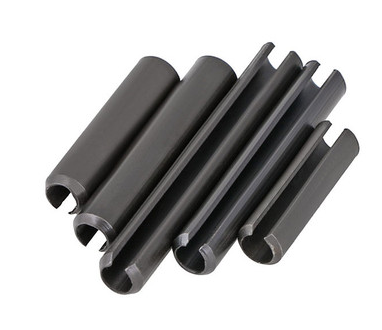
For many reasons, spring pins are used in many different components: as hinge pins and shafts, aligning components or simply fixing multiple components together. The spring pin is formed by rolling and configuring a metal strip into a cylindrical shape to allow radial compression and recovery. When properly implemented, the spring pin provides a reliable and strong joint with excellent retention.
During installation, the spring pin compresses and conforms to the smaller host hole. Then, the compressed pin exerts an outward radial force on the hole wall. Retention force generated by compression and friction between the pin and the hole wall. Therefore, the surface area contact between the pin and the hole is critical.
Increasing radial stress and/or contact surface area can optimize retention. Larger, heavier pins will show reduced flexibility, and as a result, the installed spring load or radial stress will be higher. Coil spring pins are an exception to this rule because they have multiple uses (light, standard and heavy) and can provide a greater range of strength and flexibility within a given diameter.
The example on the left shows how the protruding end of the pin remains larger than the diameter of the hole when less than 60% of the length remains in the main hole. On the right, the diameter of the protruding end of the pin is approximately equal to the diameter of the hole.
There is a linear relationship between the friction/holding force and the engagement length of the spring pin in the hole. Therefore, increasing the length of the pin and the resulting contact surface area between the pin and the main hole will result in a higher retention force. Since the end of the chamfer is not fixed, the length of the chamfer must be considered when calculating the engagement length. The chamfer of the pin must not lie in the shear plane between the mating holes, as this will cause the tangential force to be converted into an axial force, which will cause "walking" or the pin to move away from the shear plane until the force is cancelled. To avoid this, it is recommended that the end of the pin leave the shear plane by a pin diameter or larger. This situation may also be caused by tapered holes, which can similarly convert tangential forces into outward movement. Therefore, it is recommended to use a hole without taper. If a taper is required, the hole should be kept below 1°.
The chamfer of the pin must not be on the cutting plane. In this case, the pin will move in the indicated direction until the chamfer is no longer in the cutting plane.
The spring pin will recover a part of its pre-installed diameter wherever it is not supported by the main body material. In alignment applications, 60% of the total length of the spring pin should be inserted into the initial hole to permanently fix its position and control the diameter of the protruding end. In free-assembly hinge applications, as long as the width of each position is greater than or equal to 1.5 times the diameter of the pin, the pin should remain in the outer member. If this guideline is not met, it may be wise to fix the pin in the center assembly. Friction-fit hinges require all hinge components to be prepared with matching holes, and each component, regardless of the number of hinge segments, must maximize the engagement with the pin.
Browse the latest issue of Design World and return to the first issue in an easy-to-use, high-quality format. Edit, share and download immediately with leading design engineering magazines.
The world’s largest problem-solving EE forum, covering microcontrollers, DSP, networking, analog and digital design, RF, power electronics, PCB wiring, etc.
Engineering Exchange is a global educational online community for engineers. Connect, share and learn now »
Copyright © 2020 WTWH Media, LLC. all rights reserved. Without the prior written permission of WTWH Media, you may not copy, distribute, transmit, cache or otherwise use the materials on this website. Sitemap Privacy Policy | RSS
Post time: Dec-17-2020